
In the beginning of my shader series, I said that I’d stay in more in code than in graph tools. Well, today I’m ignoring that. Specifically, I’ll be going over how to work in the Unity Shader Graph. I knew eventually I’d have to start jumping into graph tools, but it has happened sooner than I expected. This post will be an intro to Shader Graph so that future posts can utilize the learning here as a foundation. This will be less an overview of the tool, and more how to translate code-shader thinking into graph-shader thinking.
Edit: Since posting this tutorial, I’ve made a video version. It does not cover the exact same demo, but does still cover the introduction of shader graph. Feel free to keep reading, or watch the video below, or both.
This article may contain affiliate links, mistakes, or bad puns. Please read the disclaimer for more information.
Why Shader Graph Now
Why am I writing a post on Unity’s Shader Graph? Aren’t there so many more topics to cover in code? Why, yes there are. But, I’ve discovered that in Unity’s new scriptable render pipelines (HD Render Pipe and Universal Render Pipe), writing code shaders got a lot more complicated. Specifically, you no longer have a Surface shader. That means if you’re writing in code, you have to manage everything yourself. I plan to write a post covering this in more depth, including how to call into Unity’s provided helpers, but not today. Today I’m doing the shader graph because with the new render pipelines, that’s the recommended way to write shaders in Unity.
To demonstrate this, I’ll largely repeat my original basic shaders post, but recreating the shaders in the graph.
Overview
There are a couple of concepts worth going over before getting into the samples.
Master node
All shader graphs have a master node. This is the final output. Anything not eventually passing data along towards that node will not be used.
Vertex and Fragment
You’ll notice that there is no way to create a unity shader graph that is specifically for vertex or fragment rendering. Graphs in Unity actually contain both the vertex and fragment shader within the single graph. Which shader each node ends up in depends on what output they drive and how Unity chooses to compile the graph. If you are driving the Position input to the master, for example, that code will end up being a vertex shader. If you are driving color, that’ll be in the fragment shader. This can be limiting as there are occasionally opportunities to do calculations in a vertex shader, then pass them to the fragment because they can be more efficiently calculated in one place over the other. Perhaps the graph compiler will see this and take advantage of it, or perhaps not. In either case, it’s outside your control.
Blackboard
On the right side of the graph there is what unity calls a “blackboard”. This is the name of the shader, and a list of all inputs. On this blackboard you can add or remove inputs.
HD Render Pipe vs Universal Render Pipe
HD Render Pipe (HDRP) and Universal Render Pipe (URP) are both built on the scriptable render pipeline, but impact your project in many different ways. This includes scene setup, and code written shaders. For shader graphs, however, there is surprisingly little difference. One of the only ones that will likely hit is if you are mucking with coordinates (none of the samples on this page are). If you are changing vertex position, where URP will us world position, HDRP uses the camera position. So URP logic flows: world space -> transform -> object space. While HDRP flows: world space -> camera space -> transform -> object space.
Full Screen Effects
With the old pipeline, the way you created a full screen shader was intercepting the render with an OnRenderImage call on the camera. I cover this in my tutorial Shaders In Unity. If you are using shader graph with the old pipeline, then this is still valid. If you are using one of the new render pipelines, this has gone away. Instead you need to utilize the Post Processing Stack. This is a bit more complex, and will be part of a future lesson.
Node Documentation
Particularly useful with the shader graph system is the ability to right click on any built in node and select Open Documentation. This will take you to the node documentation specific to that node. All (or almost all) nodes not only include a description of the node, but include a sample of what the generated code will likely look like. This is huge if you need to really optimize and understand what’s being generated.
Examples
Below are recreations of the effects in my original basic shader post, but done in the shader graph.
Sampling
To sample from a texture in the shader graph, you can either define an explicit texture asset as the source, or expose it as an input. If you are using the shader to render some image, then it would make sense that the image is an input.
To do this, you add a texture input, you click the + button on the Blackboard section of the graph, and select “Texture2D”. You can name the input whatever you want, but you do need to set one specific item to ensure this gets wired correctly. The “Reference” must be set to “_MainTex”. If you do that, then any existing renderer will understand to drive that input. Meaning, if you attach this shader to a material, and that material to a SpriteRenderer, the material and shader must have _MainTex defined as a Reference.
Once you have the _MainTex defined, you can hook that up to the input of a “Sample Texture 2D”. That node can then feed directly into your master node.

Swizzling
As discussed previously, swizzling is the act of rearranging items in a vector. Taking an RGBA variable, and rerouting it to something like BRGA. In shader graph, this is done through a node appropriately named “Swizzle”.
Simply insert this node between your texture’s color output, and the master node’s color input. From there, you specify which output channel is driven from which input. Remember that even though the channels are described as Red/Green/Blue/Alpha, that is the same as X/Y/Z/W. So if you were dealing with some position data, you might have to mentally translate “X is Red”.

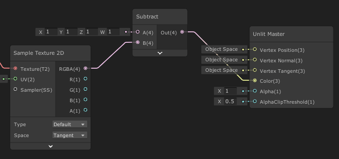
Inversion
With this we can look at a simple example of doing arithmetic within the graph. Similar to the above swizzle, we will be taking the color output from our Sample node, and doing something to it before feeding that into the color of our master node.
In this case, it’s simply feeding that color into the “B” input of a Subtract node. If you just create a Subtraction node it will default to expecting a single value for each input and output. If you wire up a vector, the node automatically adjusts.
Time Movement
This is an example of a shader that is far simpler in code than in a graph. The issue is that I want to do arithmetic on just one channel in a vector. I want to take only the X value of the UV coordinates and add _SinTime to it. In code, this is straightforward. In the graph less so. First I have to create a node for the UV input. Then I run that into a Split node to separate the channels. Now I can run the X through an Add, while the Y goes directly into a Combine node. This Combine also receives the output of the Add. So the single line of “texCoord.x +=_SinTime.x;” becomes 5 nodes in the graph.

Swirl
Well, this one is a little too easy. Unity’s shader graph comes with a node that already does this. Twirl. If you hook up SinTime to a multiply (by 10 in my case), then put the output of that into “strength” on a Twirl node, you’re pretty much done. Just feed the output into your UV sample input.

You can also do it the hard way, trying to mimic the code I had in the original post. To be somewhat helpful, Unity does provide a “Polar Coordinates” node. This will translate your uv’s into a radius and angle similar to what I did in the code. The exact values you get don’t quite mimic code though, and there is no “anti-polar coordinates” node. So doing it the hard way requires over a dozen nodes even in the best case.
Color Tint and Chroma Key
There’s a lot going on to graph this last one. It’s our first foray into branching logic and it just needs a lot more nodes to work out what’s going on. So I’m going to walk through this one in a handful of steps.
First, we sample our texture. This is no different than the other shaders, but I bring it up as a chance to mention a little tip. On the texture input you’ve created (_MainTex), you can set a “Default” texture. For in-game usage, this default is only used when nothing sets _MainTex, which almost everything does. So in-game, this default texture will almost always be ignored. However, in-graph, it’s utilized. This is helpful because you can preview the effect in-graph.

For an effect like this, the preview is really helpful to make sure it’s doing what you expect at each step.
Second section is the “black and white + tint” logic. To do this, I need to multiply the color sampled by (0.3, 0.59, 0.11, 0) and add the resulting channels together. This can be done with a single Dot Product node. I can then feed that into the RGB of a combine along with the original alpha. Then lastly multiply by my ColorTint input.

So this gets us a color tint. But now we want to only use that color tint in the areas that are not magenta to start with. This is the third, more complex section.
As discussed in my fourth shader series post, branching logic isn’t actually all that efficient. In addition, it’s kinda a pain to create in shader graph. In code, it makes things much easier to read, but in the graph it confuses things. Yes, there is a Branch node, but it’s basically just a weird wrapper around a Lerp. So I just do things in a more efficient and explicit way here.
First, I split my colors, and create two Subtract nodes: R-G and R-B. In the first case, I want to make sure R is greater than G by at least 0.12, so I feed that into a Smoothstep node. This node takes two “edges”. Anything below the lower edge is 0, above the higher is 1, and in between is a “smooth step” between 0 and 1. So this functionally becomes “if(R-G < 0.12)”. For the R-B subtraction, I do an Absolute node before feeding it into a similar Smoothstep. This functionally becomes “if R and B are within 0.1 of each other”. Multiplying the two smooth step results gives us a logical && operation. Then lastly, I feed that logical value into a Lerp node. Using a Lerp with inputs that are locked to 0 or 1, is the equivalent of an if/else (but shader efficient).

This final Lerp gives us the finished product of our shader.
At times I wish it was easier to do an if/else within the graph editor. I can’t really think of how to do it, but I sometimes wish it was there. But only sometimes. Most of the time, I’m glad that it’s encouraging the best practice of utilizing shader optimized logic (Lerp, Smoothstep, etc.).
Conclusion
Similar to the source tutorial, these are not intended to be ground breaking shaders. These are shaders designed to be simple, showing a basic concept. In this case, they also show some of the changes in mindset needed to get your thinking geared towards the Unity Shader Graph way of thinking.
This post is part of the Shader Series.
Do something. Make progress. Have fun.
I definitely want to try out Unity Shader Graph.. thanks Game Dev Bill!!