
Today’s shader tutorial is about paper. In fact, it’s the first in a collection of posts about paper. Three of them maybe? I’m not sure yet. This one is mostly about making a convincing sheet of paper.
Why so much on paper? Because real business is done on paper.
Yes, [computers] are great for playing games and forwarding funny emails, but real business is done on paper. – Michael Scott (Steve Carell), The Office
If you have any issues, ping me on Twitter, or ask on the forums.
Code & Graph
This tutorial will be done simultaneously in the built-in renderer (code shaders) and in HDRP (shader graph). I’m doing both as I prefer to explain things in code, but I’ll need things in shader graph eventually (these paper posts are building towards fire, so much fire).
This post builds primarily on two previous tutorials: vertex & geometry shaders and calculating normals in shader graph.
This article may contain affiliate links, mistakes, or bad puns. Please read the disclaimer for more information.
To give credit where credit is due, the background assets I’m using to fill out my scene are from the free HDRP Furniture Pack and PBR Game-Ready Desks Pack.
What Does Paper Look Like?
First thing we need to do is look at real paper. What about it indicates to our brain that it’s paper and not something else? Not being shiny is a good start, as is a paper-like texture. Those are relatively straightforward things to do. Sometimes paper is just flat on a table. That kind of paper is pretty boring. So we’ll ignore it. More often, paper has some variance to it. Crumples, crinkles and bumps. If they are sharp crinkles, they tend to be random. If they are more wavy, they tend to be more pronounced at the corners than in the middle. Which of these should we try to do today? I choose them all.
We’ll cover these topics:
- Setup
- Five (really four) different ways to deform a plane to make it look like paper
- An aside on sub surface scattering.
All today’s paper will be static. I’ll likely do another post soon on a page curl animation, but this post is already too long without that.
Here’s a preview of where we’re headed today.
If you’ve made it this far, and might be interested in keeping up with my work, I’d love a follow and occasional retweet @gamedevbill on twitter.
Setup
Both projects will have similar shader logic, but the setup is slightly different.
My code shader is unlit, with custom lighting I added myself (same ultra-basic lighting as in previous tutorials). That will make an ok looking paper surface. In HDRP, I just set the Smoothness input on the master node to 0.01. That’ll make it non-shiny enough to be papery. Depending on the kind of paper you want to have, you may want to tweak this number.
Scene Setup
In my built-in-renderer project, I just made a scene with the paper object in it. In the HDRP scene I did a lot more as that’s the scene I use for screenshots. I used assets from this and this asset store collection, but otherwise just used some basic HDRP lighting and post processing.
Object Setup
I’m using ProBuilder in both projects to create a plane of x/z dimensions of 9/11 (roughly a sheet of paper’s dimensions). In the built-in-renderer project, I’ll use a geometry shader to render the back side (duplicating triangles). HDRP however, supports “double-sided” out of the box, you just need to turn it on. Note that even though this is a setting in the graph matter node, you need to turn this on in the material. The master node setting is only relevant when making a new material against this shader. Meaning the master node provides defaults. I’m also going to set up subsurface scattering, but I’ll talk about that further down (in the Cheap Noise section).
For any shape, you can use ProBuilder’s “Subdivide Object” button, but if making a plane like me, use the width/height segments to break it up. I made mine 64×64, though that’s probably overkill for most situations.
Texture Setup
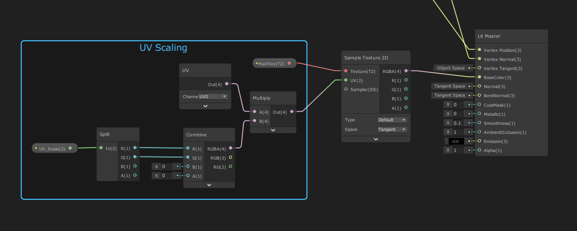
ProBuilder will setup the UV’s to have a tiled texture 9×11 times. You can fix that with their UV tools, but I find it’s easier to just put a UV scale in my paper shader.
Finding the right texture to use is important too. In the past I’ve found some good ones on unsplash.com, but for today I chose to take a photo of my kid’s drawing.

Normals and Position Setup
In the code based shader, I’ll fix the normals in the geometry shader just as I did in the vertex & geometry shader tutorial.
In shader graph, I’ll use the technique I discussed in shader graph normals. To utilize that, I’ve broken up the logic into three parts. In the middle is the actual position displacement logic. This is in one sub-graph I’ve named AllPaperNoise (because I’ll put all the displacement options in there). The rest of this article is about the various bits of logic that could go in there. It’s in the screenshot below, with a bunch of inputs and outputs, but you can ignore those details for now.
In front of the AllPaperNoise node is a sub-graph called neighbors. This contains the extensive logic from the last post that calculated the two coplanar neighbors. Then lastly, after doing the position altering, I need to take the three new points and calculate a new normal. This last stage is also in a sub-graph: NewNormal.

The Neighbors sub-graph and NewNormal sub-graph both have the exact logic in them taken from that previous post. I’ve included images of them below for clarity, but will not go into explanation of them as that’s covered in the other post. If you would like to just download them, they are in the NormalCalculation sample on my github.


Normal Maps
Before we get into manipulating vertices, it’s worth discussing normal maps. Normal maps can be helpful in communicating the surface characteristics of the paper. If the normal map is quite subtle, it can be ok on a fairly flat surface. Something more aggressive, like a map representing a heavily crumpled page, should be primarily used in conjunction with matching vertex distortion. Depending on what you are doing with your vertices, you can increase or decrease the strength of the normal map.
Adding a normal map to your paper shader is as simple as creating another texture input. This uses the same scaled UV as the texture input. The only thing you have to change on the sampler is that you set it to “type==normal”.
To dampen the strength of your normal map, multiply the x & y components by some value less than one, then re-normalize.

One detail that can trip me up at times, is remembering that in a normal map, the x & y (r & g) are on-surface, and the z (b) is pointing away. This is mainly complicated in a shader like the one we’re working on today because the position in my sheet of paper has x & z represent on-surface, and y point away.
Wavy Noise
So how shall we distort the surface in the paper shader? The first approach will be using noise functions. This is first because it’s easy. It will generally resemble some paper that got a little wet, or is well worn.
Expensive Noise
The expensive way to do this is also the easiest in shader graph. I’m just taking the provided Simple Noise node, using my XZ as the input, and adding the result to the Y value of my position.

float crumple = 0;
Unity_SimpleNoise_float(o.uv.xy, 10, crumple) ;
o.vertex.y += crumple;
Ok, this isn’t all that expensive, but it’s not the cheapest calculation either. If you view the docs on that node, and copy that a code shader, you’ll end up with quite a lot of code to execute.

Stuck in the Middle
That screenshot looks a little like paper. Sorta. It’s probably too wavy, which we could take down by multiplying the noise output. But instead, I’m going to do what we actually will want with almost any noise function, and that’s some center-damping.
A wavy piece of paper will be flatter in the middle than at the edges. Because, physics, I guess. To do that, we calculate our Y offset noise the same way as before, but also calculate a radius from the center of the paper. You’ll notice in the code below that I’m using o.uv. That’s because at this point in the vertex shader I’ve already recalculated my uv’s to be zero to one across the entire shape.
float crumple = 0;
Unity_SimpleNoise_float(o.uv.xy, 10, crumple);
float2 adjCoord = o.uv.xy - float2(0.5,0.5);
float radius = length(adjCoord*2);
o.vertex.y += crumple * radius;
For the shader graph, I can’t actually use UV’s. If you remember my vertex normal calculation logic, it requires all results to be driven by position only. So I take the input x & z, divide by the dimensions of my paper (9 and 11), and treat that like UVs.
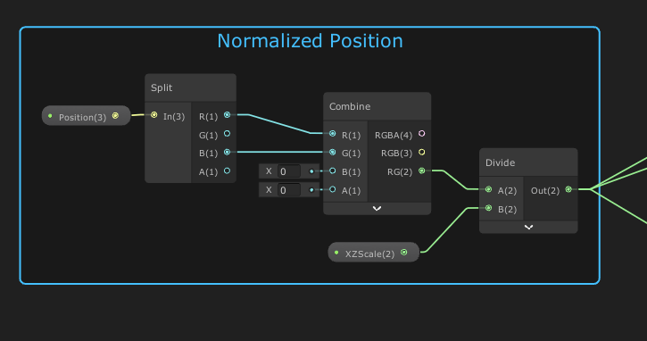
Other than tweaking how I define UV, the logic in the graph matches that from code.


Cheaper Noise
That noise node does make some really nice random noise. But it turns out I don’t need really nice random noise. A quick simpler bit of logic just uses some cosines to give the paper a more gentle wave.
Here I’m making a method with the following parameters:
- UV’s
- Overall scale
- Seed (to offset the curves)
- Frequency value called uvScale.
- The Out variable is how much to offset the Y height of the paper.
void CheapNoise(float2 UV, float scale, float2 seed, float2 uvScale, out float Out)
{
	Out = 0;
	Out += (cos(UV.x*uvScale.x + seed.x)+1)*scale;
	Out += (cos(UV.y*uvScale.y + seed.y)+1)*scale * 1.5;

	float centerRadius = length( (UV.xy - float2(0.5,0.5)) *2);
	Out *= centerRadius;
}
In the shader graph, I’m setting scale explicitly inside the shader, but feeding seed and uvScale in from the material. This gives me the ability to tweak values and see the results in real time. If they were all just in the shader, I’d have to save and recompile each time. I’ve called the input that drives both of those float2’s “DebugIn” because this sub-graph has several other noise functions that need arbitrary input. Since I’m not using them all at once, I named this something generic so I could reuse it as needed.
This cheap noise is another case where the code is easy to read & follow, but the graph isn’t quite that way.


Subsurface Scattering
I’m going to pause here to talk about subsurface scattering. Not because it is particularly relevant to this noise method, but because it’s easy to make an overly stretched page that highlights the technique. If I up the scale value in the code for this, and move my camera, I get a nice view that includes both top and bottom sides of the paper.

In the screenshot above, you can see both a top-side shadow, and the unicorn face showing through to the bottom of the paper. This is due to an effect called “subsurface scattering”.
Essentially this effect has to do with materials having some level of thickness, that if low enough, allows light from one side can shine through to the other. Overall, this is a large topic to discuss, I’m just mentioning it to say that you’ll want this enabled for paper.
I may eventually write a longer post on how to set this up, but for now, here is the short version of how to set this up:
In the built in renderer – do a lot of work. This is a hard task and for now I’ll refer you to a write up by Alan Zucconi on it here.
In Universal RP – things are less hard, but also less free. From what I could dig up, the easiest and best result out there in URP is to use Lux URP.
In HDRP – things are easy and free. You basically just turn it on. It’s a setting in the shader graph to enable, then you just add a profile. I created a profile and didn’t change anything from the defaults. Turned out good enough for these tests.

Creases
The next technique we’ll explore is adding some creases to the paper. This is where you have a defined line at which the page takes a hard turn. I found that four creases was enough to make things look pretty good. For a single crease, I used this code:
float4 CreaseNoise(float2 UV, float4 inVerts, out float4 lineEval)
{
	float4 outVerts = inVerts;

	//float4(a,b,c,d) where
	// line: y = ax + b
	// strength: c
	// sign for arithmetic: d
	float4 downLine1  = float4(-0.4, 0.2, 3.2, 1);

	lineDist.x = UV.x * downLine1.x + downLine1.y - UV.y;
	float movement = downLine1.z * saturate(downLine1.w * lineDist.x);
	outVerts.x += movement * -0.5 * sign(downLine1.x) * downLine1.w;
	outVerts.y += movement;
	outVerts.z += movement * 0.5 * downLine1.w;
Then I repeated that three more times with these values:
	float4 downLine2  = float4( 0.7, -0.5, 0.7,  1);
	float4 upLine1    = float4(-1.0,  1.2, 0.9, -1);
	float4 upLine2    = float4( 1.4,  0.6, 1.2, -1);
Let’s walk through the logic. First, I define my data in a float4. This defines a line with the formula y = line.x * x + line.y. Then line.z is used to determine the strength of the bend. And lastly, line.w is used purely for it’s sign to alter the direction of some arithmetic.
To pull this off in shader graph, I’m going to make a subgraph within my subgraph. The inner graph will just be the math done on a single line. It’ll take in a line definition float4 (LineData) as well as the float2 UV’s. Of note, I actually use the LineData input twice in this graph. This is just to reduce the number of overlapping lines.

The next level of sub-graph is what actually alter’s the position. I use the same “Normalized Position” math found in earlier in this article to turn the position into a UV like number. Then feed that plus four different LineData’s into four different crease subgraphs.

You’ll notice all four of my Lines are setup as inputs to this graph. I feed that all the way up to the material so that I can easily control them live in-scene.
At that top level, things are similar to the previous noise functions, with one key difference: I reuse some position information in the fragment shader area. Looking at the first subgraph, you can see I take an intermediate value from our calculation (LineDist) and feed it up as an output. Then, at the subgraph above that, I combine all four LineDist outputs into a Vector4 output. These four float values represent a signed distance from each line. I use that to feed some logic that will darken the color along the creases. In code it looks like this:
float4 lineDist;
CreaseNoise(i.uv.xy, float4(0,0,0,0), lineDist);

float crease = 0;
crease += saturate(abs(lineDist.x) * 50);
crease += saturate(abs(lineDist.y) * 50);
crease += saturate(abs(lineDist.z) * 50);
crease += saturate(abs(lineDist.w) * 50);
crease *= 0.25;

col.rgb *= crease*0.4 + 0.6;
I grab the absolute value of the signed distance, scale it way up, then saturate (which takes any value above 1 and clips it to 1). I average the four distances, and get a value that is 1 unless it’s close to one of the lines. The last line of code scales the color down when I’m close to a line. How much can be determined by your case, but I went with a 40% max darkening.
It’s a bit hard to read in the graph, but here’s the full top level crease paper shader. It takes the 4 lines in, feeds them to three copies of the CreaseNoise subgraph (main, and two alternate positions for normal calculation). The fragment logic that darkens near the creases is highlighted


Texture Sampling
The last technique I’ll discuss is using a texture to determine the vertex offset. Believe it or not, you can sample a texture inside a vertex program. You do so with the method tex2Dlod().
To set this up, you’ll want a texture that contains the height of your offset encoded into a color channel of an image. For this sample, I used a tool called Filter Forge to generate that height map. I use it stand-alone, but it can also be a Photoshop plugin.
Since it is a pay-for product, I won’t just give away the generated textures here, but I will recommend the tool. I’m an affiliate, but they don’t have a very well setup program, so here’s a link to their homepage, which is the link you could find useful (it has actual information), but is not an affiliate link. If you do decide you want the tool, I’d appreciate you using this link for Windows or this one for Mac, as those link my affiliate account, but neither link has any useful information.
In addition to a height map you’ll likely want a normal map. I used Filter Forge to generate mine as well, but Unity can generate a normal map from any height map as well (on the texture importer settings).
As I said at the beginning of the tutorial, you’ll generally only want to use a normal map that has serious variance to it if you are in lock step with a height map. That’s what I have here. My vertex code will call this:
void TextureNoise(float2 UV, float scale, out float Out)
{
	float4 height = (tex2Dlod(_NoiseTex, float4(UV, 0,0)) )* scale;
	Out = height.r;
}
And in my fragment code, I sample the normal map. In this one instance I am not recalculating normals in my vertex or geometry programs. While my setup for calculating those is ok, it works best on smooth curves. Here I’ve got ragged edges, and I have a much more precise input to use. So sampling the texture comes out much better.

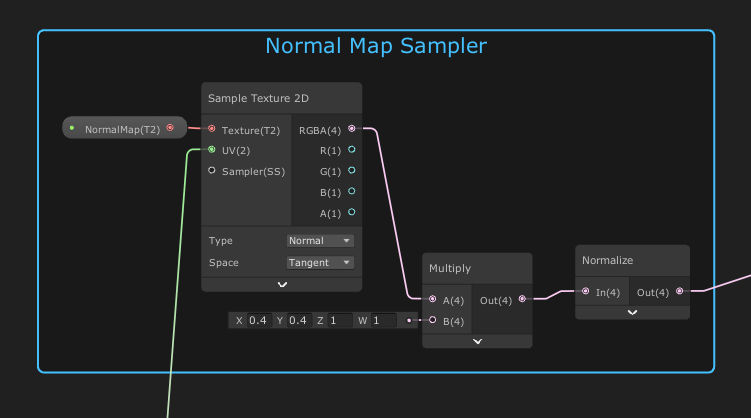
You’ll notice that I multiply the output of the normal map sampler by (0.4,0.4,1). This weakens the sideways components while leaving the vertical alone. Essentially making the vector point slightly more towards the Z direction. Then, after re-normalizing it, I get a new normal vector that is my sampled texture, but dampened slightly. I would ramp up the strength of this normal map in conjunction with the strength of my height sampling in the vertex program.

If you only look at the center of the paper, and the camera isn’t moving, it can be hard to tell if the shadows are just normal map trickery, or if the vertices are actually offset. Looking at the edges makes it clear (as would moving the camera around). Below is the full top level graph for this paper shader. I kept the group “Normal Calculation” in there to highlight that it’s missing (this was the group that had the two extra position calculations to recalculate normals). This group isn’t needed since we can sample the normal we want.

Roads Not Traveled
So, that’s a really long post just about the basics of paper. I covered four main ways to make paper look more like paper: Random noise, cheap noise-ish (cosine), creases, and texture maps.
I have more things I want to talk about, but they’ll have to be reserved for future posts. Perhaps: burning paper, page curl/turn, rendering another scene as a drawing, making arbitrary meshes be paper, etc. Fire is almost certainly the next one on the list, but if you have a preference of what you’d like to see next, please post in the comments below or hit me up on twitter @gamedevbill.
Do something. Make progress. Have fun.
Hello Bill, thanks so much for such nice tutorials. I’ve been following your tutorials but was having a hard time understanding the concepts well. I found that you shared the demo for the burning paper tutorial, so I wanted to look that as a reference, but the project didn’t seem to work for me (the paper doesn’t show up in the scene for some reason. The other two tutorials worked without issue). By any chance, can you share the paper shader project with different ways to deform on your GitHub? My goal is to build realistic paper on Unity like how you achieved in this post, and looking at the actual demo will help me a lot. Thank you!
Yeah, I’ll take a look and see if i can get it figured out
Thank you!
Ok, I just checked in some tweaks to make the sample make a little more sense. Open up Assets/Scenes/Paper.unity
Does that help? Let me know how things are working for you, in case i misunderstood your ask.
Thanks so much for sharing your work! I just checked the demo and it is amazing. The project is working without issue now, and looking at the graphs gives me a better understanding of the shader. The part where I was having a hard time, for example, was when I was trying to follow the Creases method. It seems like for the final CreaseNoise Node, I need to have inputs “XZscale” and “PositionScale”, but I wasn’t sure how this is put inside the subgraph. There were several moments when I had similar questions, and this was the reason why I thought looking at the whole graph/subgraph will give me a better understanding. It will be great for me if graphs for the different methods (creases, cheap/expensive noises) are also included inside the demo, but just looking at the paper burn example already gives me so much more opportunity for learning. Thanks a lot!